Revised 08/18/02
Early Cessna 150 Inspections, Tips,
Tricks, and Hints
Email me at hannacm@charter.net
Visit Charles' and Dusty's Homepage
Return to the Early Cessna 150 Inspection Homepage
150 home / Charles's Home / Misc Items / MLG Insp / Firewall / Rudder & Vertical / Tailcone / O-200 / O-200 Oil Flow / Props / Jacking / Shoulder Harness / Links / Owner Mfg Parts / Owner Maintenance / IO-240 Dream Engine
Main Landing Gear
Legal stuff: The material presented below is for educational/entertainment/reference use only and should not be used as documentation in the inspection and repair of any aircraft. You should always consult the Manufacturers FAA/CAA approved documentation such as Maintenance Manuals, Service Letters and Bulletins, Kit instructions, STC's, etc. for inspection and repair information and procedures. I make no claim or warranty as to the accuracy or completeness of the material presented, and accept no responsibility for its use or misuse. Also, this web page or any other of mine, is not connected with, or approved or sanctioned by Cessna Aircraft Corp. or any other entity named herein. Charles M. Hanna
Lets start with the expensive stuff, the landing gear. 150's s/n 15059379 and EARLIER have a multitude of problems with the Main Landing Gear structure. It simply wasn't sturdy enough, and cannot stand any sideloading or rough runways. Cessna saw the problem early on and created Service Bulletin's to require inspections of the problem areas and Service Kits to reinforce the areas, but still not to the extent of the later aircraft.
The first letter was a Cessna Service News Letter (SNL) 150-28 dated 11-17-61 and calls for the "main gear support brackets" to be inspected at the first 500 hours and thereafter at 300 hour intervals. If problems are found the letter calls for installation of Service kits 150-6, SK150-7 and SK150-8. It is no longer possible of course to obtain the kits, though some of the individual pieces contained in the kits might still be had from Cessna. In the photos that follow I will show you how to determine which kits, if any have been installed, and show what problems might result from the installation of the kits.
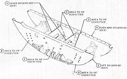
The terminology is as follows: the two bulkheads that run laterally across the aircraft just behind the seats and below the floor are the "forward bulkhead" and the "aft bulkhead". The gear legs lie between these bulkheads. There are four fittings mounted between these two bulkheads, two are the "inner bulkheads" and are where the inboard ends of the gear legs attach, and two are the "outer bulkheads" (or fittings) and are the ones under which the gear legs pass and to which they are attached via square "U" bolts.
Begin your inspection by removing the seats completely, the carpet in the bag compartment, and then removing the two large inspection panels in the seat pan under the seats. Remove the two inspection panels in the bag compartment floor, and, in the floor that is the top of the "gear box" remove the one round and the two "parallelogram" plates (if SK150-6 HAS been installed) or the two round plates (if SK150-6 has NOT been installed). Also remove any small snap in plugs over the nuts on the u-bolts. One of these plugs on each side is underneath the plastic doorpost trim and you will need to carefully remove the trim, as it is usually cracked in numerous places. On the outside loosen (you cannot get it completely off) the plate around the gear leg opening on both sides and pull it down the gear leg. This will expose a slot inboard of the gear leg opening that allows the u-bolts to be removed or inspected.
You will need several small inspection mirrors of different sizes and preferably one which has a remote control on the handle (snap-on). If you can obtain a boroscope it will also be very handy for some of the difficult to reach areas. You also need a good bright light such as a rechargeable mag light and also a small flourescent trouble light you can put down in the under floor area.
Begin your inspection by getting underneath the landing gear and inspecting the u-bolts thru the slots in the belly. Examine them carefully to see if they are cracked or broken, as they have tight, sharp, 90 degree bends they are prone to cracking in the bends just forward and aft (below) the gear legs. With the nose wheel chocked, have someone grab the gear leg near the wheel and violently shake it fore and aft, while watching to see if the gear leg slips in the u-bolt. While underneath look closely at the two rows of rivets running across the belly where the forward and aft bulkheads are riveted to the skin, for cracks and loose rivets.
Next, inside the cabin, place the flo lite underneath the bag compartment floor and using a mirror, look forward thru the access holes in the bag compartment floor. You will see two rows of pin rivets forming a "V" shape in the center of the backside of the aft bulkhead. Pay special attention to the topmost two in each row. Look for starburst cracks around them, and oil or "soot" that indicates that the fasteners are loose and working. These are steel pins with grooves in them and have aluminum collars driven up on to them. The collars are somewhat cone shaped, and are all found on the back side of the aft, and front side of the forward bulkheads. Reach in and attempt to turn the collars, if they are loose or shows signs of being loose or working, make notes and press on. Do this anytime you find something wrong, make sketches, notes, etc. and continue inspecting.
Look outboard on the aft bulkhead, you will see two rows of four pin rivets on each side, inspect them in the same manner as described and examine the bulkhead for cracks around or thru the fastners.
On the back side of the aft bulkhead, if you see what appears to be very heavy doublers at the top of the aft bulkhead in the middle, and underneath all eight fastners on each side at the outboard fittings, and the fastners where the doublers are mounted are AN, MS or NAS bolts and nuts, and rivets, the gearbox has already had SK150-7 installed.
Next go to the front side of the front bulkhead, put the flo lite under the seat pan and position it to illuminate the bulkhead. Using all possible mirrors and combinations of standing on your head, etc., examine the forward bulkhead as you did the aft, both at the two rows ("V") of fastners in the middle, and the eight at each outboard fitting. You are most likely to find cracks at the top two in each row of the "V", but look all over and check all of them for looseness. If SK150-7 has been installed there will be a doubler in the middle top section of the bulkhead, attached with bolts and nuts and rivets.
Now for the tough part, the inspection of the interior of the gearbox. If the floor over the gearbox has two squarish "parallelogram" inspection plates in it over each outboard fitting, and a single round inspection plate in the center of it, it is most likely that SK150-6 has been installed, there are some other parts of the kit to look for and they will be covered later, or in the photos. If the floor over the gearbox has two round inspection plates in it and no "squarish" ones, it most likely has not had SK150-6 installed.
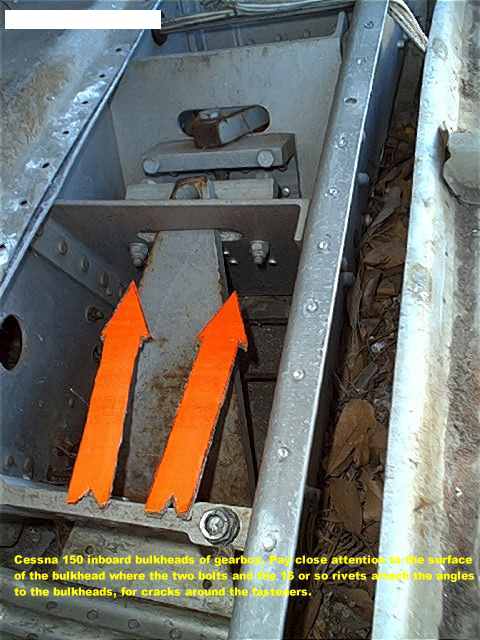
The original floor with two round plates will give you access to the inboard bulkheads, and the angles to which the inner end of the gear leg is bolted, and will also allow you to see the inboard side of the outboard attach fittings. If you have an unmodified gearbox procede by inspecting the inboard bulkheads in the upper fore and aft radius's for cracks. also inspect these for cracking of the bulkhead where the rivets attach the heavy angles that the bulkhead underneath the gear leg. This is difficult to see, a boroscope will help immensely with the inspection of the interior of the gearbox.
Looking outboard you should be able to see the gear leg pass underneath the outboard fitting and also see the u-bolts where they emerge from the bottom of the fitting and run underneath the gear leg. Examine the u-bolts closely for breaks or cracks, and if possible, get a wrench on the two nuts on the top of the fitting and check for tightness (or looseness if you are a pessimist).
Now for the nearly impossible part. With an unmodified gearbox you may be able to remove two one inch metal plug-buttons from each side of the floor and see some of the area outboard of the outboard fitting. These plugs are provided to give you access to the nuts on the top of the u-bolts. Cessna SNL150-28 actually calls for jacking of the aircraft by the wings and removing the gear legs to inspect the area outboard of the outboard fitting. In the future I will add a page on wing jacking and how to do this.
If you have a boroscope you will be able to fish it into the area outboard of the outboard fitting. If a corrugated looking stiffner running from the front to the rear bulkhead againist the outer skin and a flat plate bracket running from the fitting to the outer skin is present, this is an unmodified gearbox (no SK150-6) and the flat bracket will most likely be broken. If you are looking down on the top of an open top steel "box" which is fastened to the outboard fitting and to the outer skin, then SK150-6 has been installed.
My 150 had holes wacked in the original floor over this area and had the steel "boxes" installed, but none of the rest of SK150-6. The holes were covered over with "inspection" plates roughly cut out of flat sheetmetal. Needless to say this has all been replaced now.
Lets go thru the photos and their accompanying text, then I shall show you what problems Cessna CREATED by installing the steel "boxes" that are part of SK150-6.
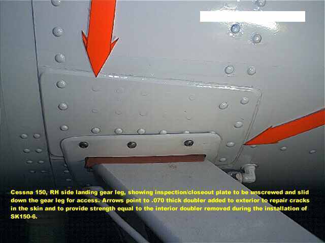
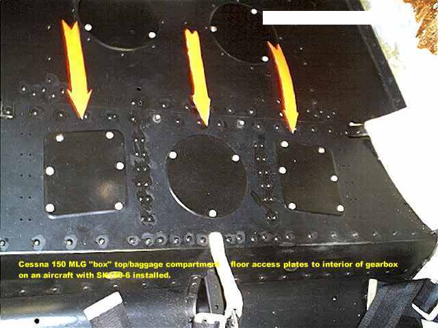
The next four photos show the access plates that need to be removed to access the landing gear for inspection.


This next photo shows the area on the aft bulkhead at the inboard bulkhead attachment and the inspection holes to look thru to see the rear of the bulkhead. you will also want to look closely at the outboard ends of the bulkhead where the outboard fittings attach with the eight fasteners each.

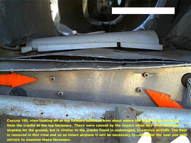
This next shot shows the front side of the forward bulkhead with the gearbox cover/floor panel removed. To see this bulkhead on an inservice aircraft, you will need to look thru the two large inspection holes in the seat pan and use mirrors to look back and up at the bulkhead. look at both the two rows of fasteners (the "V") in the center and the eight attaching each outboard fitting to the bulkhead. While these cracks were caused by impact during a windstorm, it is similar to what you will see on an inservice aircraft.
Now for some views of the gearbox interior inspection. These were made using a wind damaged 1962 model with the early type gearbox. The floor over the gearbox has been removed to provide a better view of the insides.
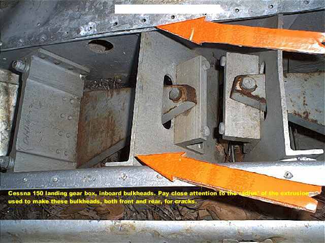
Below. This is sorta what you would see looking thru the inspection holes of an unmodified aircraft. Pay particular attention to the OB flat surface of the inboard bulkheads around the nuts and rivet tails for cracking. Also look closely at the radius' of the extrusion used to make the inboard bulkheads, as they are prone to cracking in the top edge of the bulkhead.
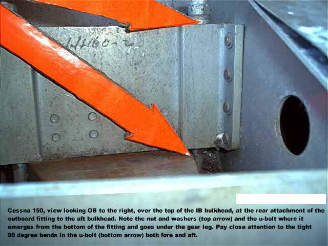
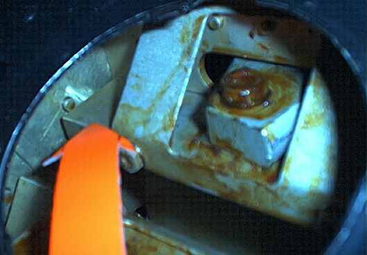
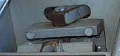
Below is a shot looking OB and slightly aft at the IB face of the outboard fitting. The arrows show the nut, washers and 90 degree bend in the back leg of the u-bolt. You can also see the other nut and 90 bend on the forward leg of the u-bolt, The 90 degree bends are the problem area.
Below, this is a view looking down on the outboard fitting, the outer skin of the aircraft is on the left. The top arrow points to a corrugated doubler that is atttached to the skin and on the ends it connects to both the front and back bulkheads. Sandwiched between the doubler and the skin is a steel bracket (lower arrow) that runs inboard to the outboard fitting. This bracket is extremely prone to cracking as this one is, just below the four rivets. These two parts were replaced by a welded steel, open topped "box" which bolted to the outboard fitting and to the skin where the doubler was riveted.
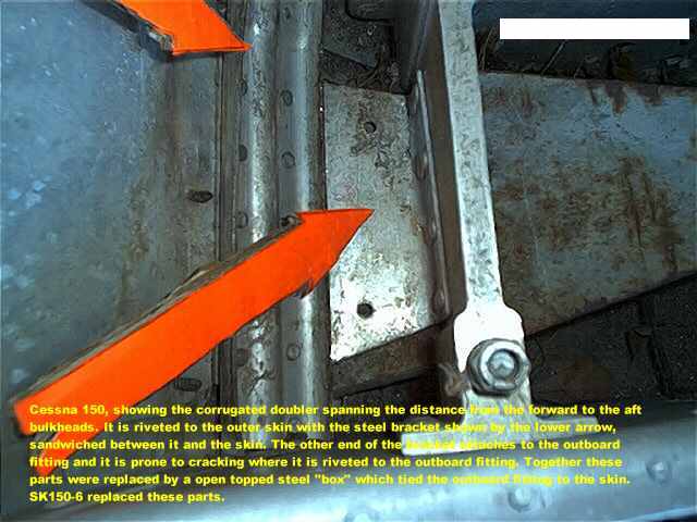
The problem with the installation of the Service Kits is that the steel box placed tremendous side loads on the .050 skin without any other reinforcement. The front and aft bulkhead flanges are riveted to the skin also and the end result is that the skin cracks along the narrow space between the steel box and the bulkhead flanges. I repaired this on my airplane using the doubler shown previously
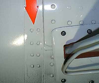
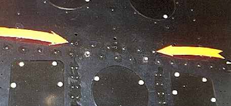
The end result of my doubler is that the steel box transfers the side loads to the .050 skin and the .070 doubler layered over it, and both the skin and doubler transfer the loads back to the forward and aft bulkhead flanges, which the skin by itself cannot do for long without cracking. On an airplane which has had SK150-6 installed inspect (with the closeout plate removed) the exterior skin directly above the gear legs and in line with the front and back edges of the legs.
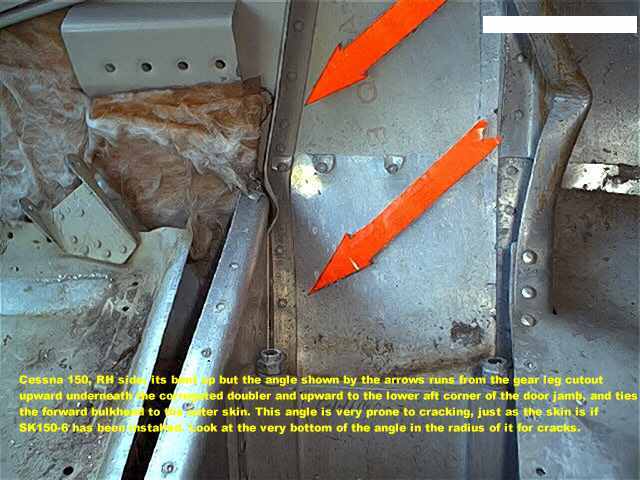
In addition to cracking the skin the stresses placed on the skin by the steel box also cause the 3/4 inch aluminum angle shown by the arrows below to crack at the very bottom of, which is at the forward upper corner of the gear leg cutout. This angle has compound curves in it, following the curvature of the fuselage as it goes upward and at the top of the bulkhead it turns aft. Cessna no longer has these and it is extremely difficult to form these, but it has been done.
How to identify if the Cessna service kits have been installed.
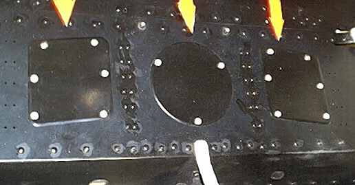
If SK150-6 has been installed,
you will see a floorboard that looks like this:
(note the double row of
rivets between the inspection plates, that is part of the kit)
(this is standard and factory
installed after s/n 15059379)
Also if SK150-6 has been installed, the Inboard attach angles (the thick part the bolts pass thru, just under the arrow) will be reinforced as shown and If SK150-8 is installedthe attach angles will be extra long as indicated by the tip of the arrow: The reinforcement is factory installed after s/n 15059379, however the extra long angles are peculiar to SK150-8 and will not be found factory installed.
Compare this with an unmodified aircraft: It is possible to find an aircraft which had SK150-7 installed without SK150-8 and you would see the reinforcement with the short angles. This also would be a factory configuration after s/n 15059379.
If SK150-7 has been installed you will see an additional row of rivets on the bag compartment floor as indicated by the arrows. This is peculiar to the Service Kit and was never done at the factory.
Also if SK150-7 is installed you will see two vertical rows of 4 rivets just aft of the skin lap behind the gear legs. This also is peculiar to the Service Kit and was never done at the factory.