Email me at hannacm@charter.net
Visit Charles' and Dusty's homepage
Return to the Early Cessna 150 Inspection Homepage
150 home / Charles's Home / Misc Items / MLG Insp / Firewall / Rudder & Vertical / Tailcone / O-200 / O-200 Oil Flow / Props / Jacking / Shoulder Harness / Links / Owner Mfg Parts / Owner Maintenance / IO-240 Dream Engine
Rudder and Vertical fin Inspection
Legal stuff: The material presented below is for educational/entertainment/reference use only and should not be used as documentation in the inspection and repair of any aircraft. You should always consult the Manufacturers FAA/CAA approved documentation such as Maintenance Manuals, Service Letters and Bulletins, Kit instructions, STC's, etc. for inspection and repair information and procedures. I make no claim or warranty as to the accuracy or completeness of the material presented, and accept no responsibility for its use or misuse. Also, this web page or any other of mine, is not connected with, or approved or sanctioned by Cessna Aircraft Corp. or any other entity named herein. Charles M. Hanna
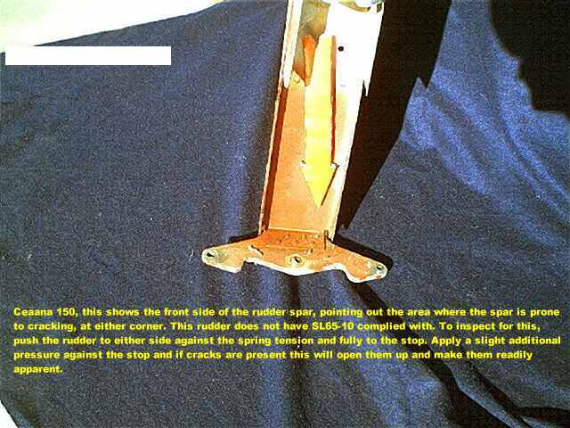
The rudder on the straight tail 150's was in the beginning, rather poorly designed, and as a result the spar in it was very prone to cracking in the lower corners. Two service letters addressed the weakness'es of the rudder by incorporating additional stiffners that were phased into production.
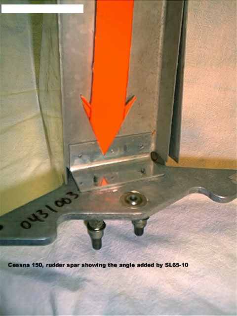
Service Letter 65-10 calls for the installation of a small angle at the bottom of the spar where the lower rudder bellcrank is riveted to the spar and the lower rib. I have seen quite a few homemade field installed stiffners added in this area of the rudder, they vary in size and shape and quality of installation, but you can be sure that if one is present then there is a cracked spar beneath it.
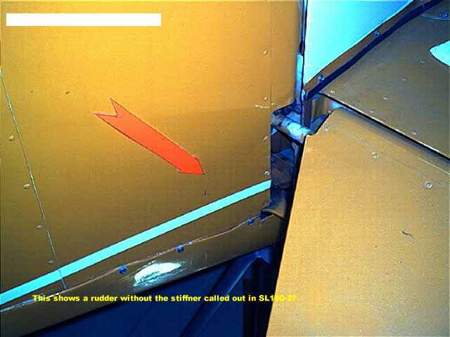
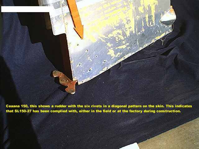
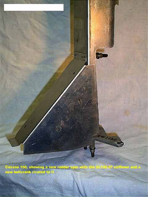
To provide additional stiffness to the lower forward corner of the rudder, Service Letter 150-27 calls for the installation of a triangular shaped stiffner inside the rudder which is riveted to the spar web, spar flanges, lower rib web and lower rib flanges, and to the skins on both sides. This piece adds considerable strength and rigidity to the rudder.
Examine the two photos below, which show a rudder without the SL150-27 stiffner, and one with it. The only visible difference will be six additional rivets in the skin on each side in a diagonal pattern.
Below is a view of the rudder spar with the area indicated that is prone to cracking. It is quite common to find homemade field repairs to this area of the rudder, however the only additional part which belongs in this view is the stiffner called for in SL65-10, which is not show here.
Below are three views of some new parts clecoed together to depict a rudder with its skin and lower rib removed. Should you find any other kind of stiffeners on the rudder, they are "homemade" and are not Cessna parts.
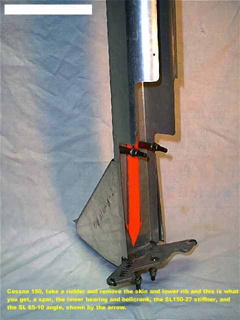
If you will notice, the lower bearing for the rudder is made into the bellcrank. It is quite common for the bearing to be extremely worn. Due to the rudder cable spring tension you will not notice it easily. Push the rudder to a stop, push harder while watching the bearing, you will see the slop in the bearing, as this procedure will force the rudder aft against the spring tension. (this same technique works extremely well for inspecting the center elevator hinge bearing) The bearing wears in part because the weight of the rudder is exerted down on the spherical ball. To take the weight off the bearing, Service Bulletin 65-75 called for the installation of a p/n S1003-78 thrust washer underneath the bearing. The washer is made of bronze oillite and carries the vertical loads (weight) of the rudder, and transfers these loads directly to the lower lug of the hinge fitting on the aircraft, leaving the bearing to do the pivoting and carrying the forward pull of the rudder cables. The thrust washer is easily lost when the rudder is removed and you should check to insure it is in place during reinstallation of the rudder.
Speaking of rudder cables,
these are one of the most misunderstood items in a 150 of any vintage.
The rudder cables more prone to becoming excessively stretched than any
cable in the aircraft. Why?? because the pilot is constantly pushing on
both pedals, and sometimes, such as when using both toe brakes simultaneously,
considerable pressure is applied to the rudder pedals, thus pulling on
both cables. This wears the lower bearing, the bushings and bellcrank where
the cables attach, and most of all, it stretches the cables. How do you
know this?? Using the maintenance manual you will find that the purpose
of the turnbuckles on the aft end of the cables at the rudder is not to
set the tension, but rather to set THE DISTANCE OF THE RUDDER PEDALS FROM
THE FIREWALL!!! This indirectly sets the tension if the two springs are
in good condition and working order. When you have run out of turnbuckle
and the pedals are still too close to the firewall, you know they are stretched.
The cables I removed from my airplane were about 3/4 inch longer than the
new cables I obtained from Cessna.
------
RUDDER CABLE, PEDAL STEERING RIGGING
First, disconnect both nosewheel steering rods at the steering collar.
Second, remove the cover over the "hump" in the center of the floor. (this is a lot of work) This exposes the forward end of the rudder cables where they attach to the rudder bar tabs. Look carefully to insure that the springs are installed from these same tabs to a tab on the structure about four inches forward. If the springs are broken, weak, or missing, replace them before going any further. I have found springs missing from the factory on brand new 152's before and it is not uncommon to find the springs unhooked from one end or the other. It is inperative that they be in good condition and of proper and even tension.
Third, take a rod such as a welding rod and grind a fine point on it to penetrate the firewall insullation blanket to the sheet metal of the firewall. Cut the rod to exactly 5 1/2 inches in length. The pedals you will be dealing with are the pilots Right and Left pedals. Block the rudder itself in the netural position. Using the Maintenance Manual for the correct data, adjust the turnbuckles to obtain the proper height of the pedals. On a 150 this would be 5 1/2 inches from the backside of the steel sheet of the firewall to the pivot point of the pedals. Safety the turnbuckles.
Fourth, Fully extend the nose strut, this centers and locks the steering collar, then pull the steering rods firmly out againist the bungees inside them, but not compressing the bungees. Adjust the clevis ends on the steering rods to connect the rods to the rod ends protruding from the sides of the steering collar (***the distance from the center of each of these rod end bearings to the face of the steering collar where the jamb nut seats is 1.25 inch***) with a free bolt where it attaches to the steering collar rod ends, and no freeplay in the rod. Remove the rudder blocking you installed previously. Close the floor "hump" cover but first look carefully for things loose, cracked, and rubbing. Most common is the rudder cable on the copilot side sawing on the fuel line.
Fifth, go fly the airplane in smooth air at a normal power setting in cruise. Be sure that if you have a trim tab that someone has added to the rudder (there should be none) it is faired with the rudder (or removed). If it needs a slight amount of right or left rudder, you can tighen up or loosen up the turnbuckles slightly. This will give you some "trim" in that direction via the springs, whose real purpose is to tension the cables and keep them from being slack and causing a sloppy rudder. In flight the torque links will be fully extended, locking the steering and preventing the steering collar from turning. Thus in flight when you push a rudder pedal, you are also compressing one of the steering bungees, and it is the bungees that give you the feel and centering of the rudder in flight.
Sixth, DO NOT as many people
do, off center rig the steering bungees to kick the rudder off center to
make an out of rig airplane fly straight.
-----
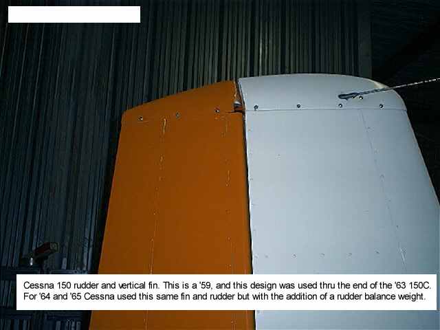
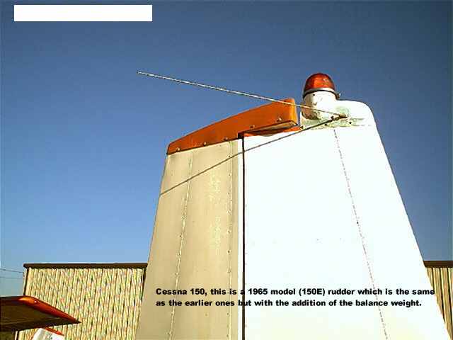
For comparisons sake, below is two views of the top of straight tail rudder showing the difference between the '59 thru '63 rudder and the '64/'65 models with counterweights. The 1966 150F introduced the swept fin and rudder.
VERTICAL FIN
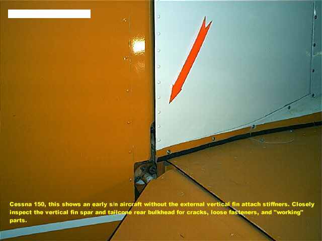
The problem area on the
early 150 vertical fins was with the aft attachment to the rear tailcone
bulkhead. Cessna issued a Service Kit, SK150-3 which installed four
stiffeners on the vertical fin spar. The spar is channel shaped and fits
inside a channel shaped bulkhead on the tailcone. to add additional strength,
a stiffner was added on the outside of the vertical fin spar on each side.
The stiffener overlapped the the outside of the tailcone bulkhead.and this
is what they look like, and for comparison, an unmodified aircraft. They
were incorporated into production beginning with s/n 15059067 (an early
1961 150A). What you cannot see with the rudder installed are the two stiffeners
the kit also installed, which are angles running up the inside of the rear
spar channel. They added considerable stiffness to the vertical fin.
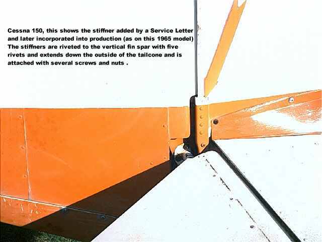
Compare the view below with the one above and you will see the difference. In the view below you can make out the outside of the tailcone rear bulkhead flange just below the left hand end of the black rubber strip. In the view above it is covered up by the stiffener.