Revised 08/18/02
Early Cessna 150 Inspections, Tips,
Tricks, and Hints
Email me at hannacm@charter.net
Visit Charles' and Dusty's Homepage
Return to the Early Cessna 150 Inspection Homepage
150 home / Charles's Home / Misc Items / MLG Insp / Firewall / Rudder & Vertical / Tailcone / O-200 / O-200 Oil Flow / Props / Jacking / Shoulder Harness / Links / Owner Mfg Parts / Owner Maintenance / IO-240 Dream Engine
TCM O-200A Inspection and tips
Under construction, more text and photos coming, please bear with me
Legal stuff: The material presented below is for educational/entertainment/reference use only and should not be used as documentation in the inspection and repair of any aircraft. You should always consult the Manufacturers FAA/CAA approved documentation such as Maintenance Manuals, Service Letters and Bulletins, Kit instructions, STC's, etc. for inspection and repair information and procedures. I make no claim or warranty as to the accuracy or completeness of the material presented, and accept no responsibility for its use or misuse. Also, this web page or any other of mine, is not connected with, or approved or sanctioned by Cessna Aircraft Corp., Teledyne Continental Motors (TCM) or any other entity named herein. Charles M. Hanna
For a discussion on oil system flow and circulation in the O-200 engine, visit my web page, "Oil Flow 101 for Cessna 150 and O-200A owners"
View the FAA Type Certificate Data Sheet (TCDS) E-252 for the Teledyne Continental Motors C-90 and O-200 model engines. This copy is loaded from my web site, if you prefer to have it load from the FAA's web site, CLICK HERE and you will be taken to a web page at the FAA's web site. On this page just click on the Adobe logo and you will download the PDF file for TCDS E-252.
Problem areas....
Crancase studs
I have experienced on two
occasions, different cases, twenty years apart, of studs pulling out of the case on an O-200A. The folks at Divco,
who probably do more case repairs than anyone else in the country, tell
me that this is a chronic problem with this engine. The studs which are
the problem are the thru studs, those that screw into one half of the case
and pass thru the other half. There are four located at the front of the
case on the left side and three at the rear of the case on the right side.
Two of the froward ones are used as cylinder holddowns for number four
cylinder, and two of the three at the rear are also used as cylinder holddown
studs for number one cylinder.
Divco's fix is to pull all seven studs and install self locking heil-coils in the case and reinstall the studs. This procedure is not TCM approved, it is, however FAA approved for Divco as a repair process. Divco tells me they do not have any "comebacks" after having done this to a case.
Oil temp probe difficulities
The older 150's have a mechanical oil temperature gage. The temp bulb in the oil screen on the back of the engine has a metal tube connected to it which runs to the gage in the instrument panel. This is a sealed unit and if broken open, crushed or damaged in almost any way, will not function. The entire gage/bulb/tube assembly must be replaced as a unit and is no longer available new.
The biggest problem is the 5/8 hex "nut" that retains the bulb into the steel adapter, which is, in turn, screwed into the brass oil screen "nut". Removing the screen for cleaning during oil changes requires that you unscrew the 5/8 hex "nut" and pull the bulb out of the screen. You then cut the safety wire and using a one inch open end wrench, remove the brass screen "nut" to which the screen is attached, and the steel adapter fitting for the temp bulb.
This 5/8 "nut" is very thin walled, and the flats of the hex are only about 1/8 inch wide. This nut cannot be replaced as it is put on before the temp bulb is soldered to the tube and "charged "
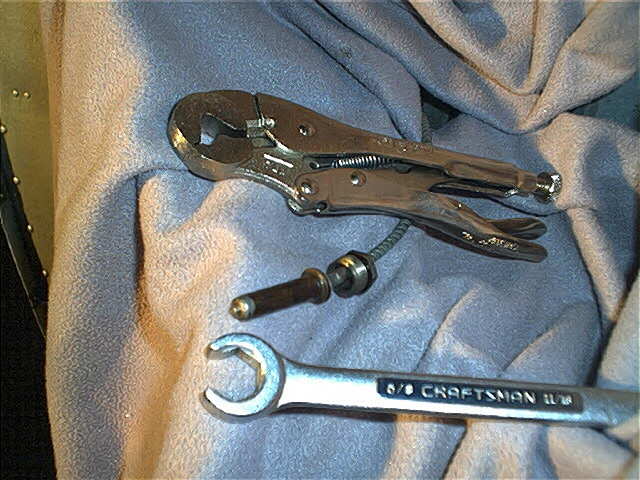
I say all of this only to warn the unwary that the proper tools are a must for removing and installing this temp bulb repeatly without damaging it. The best tool to use is a 5/8 inch, 6 point "line wrench", which will give the most surface contact with the thin nut without damaging it. DO NOT use an open end wrench, as the nut will be rounded off. If the nut is rounded off, the best choice of tools seems to be a special pair of vice-grip pliers with a special jaw, which can clamp down on three of the six flats of the nut. It is a p/n 7LW. Care must be exercised when using this, to not crush the nut.
Below is a pic of the temp bulb and both of my suggested tools. The thin hex nut which I referred to is the threaded sleeve with hex that is on the tube with the temp bulb. When screwed into the adapter on the engine oil screen, you only see the thin hex and not the threads.
Should you break off the tube or otherwise damage the bulb, it may be possible to have it repaired. While I do not have any personal experience with the firm, I have been told that the John Wolfe Company, which is in the business of restoring antique auto and aircraft instruments can repair the bulb/tube/instrument. I received an email from a gentlemen who recommends them thru personal experience with the mechanical oil temp gage in his older Cessna 172.
Pushrod tube leaks
Anyone who has ever dealt
with a small A or C series Continental engine is familiar with pushrod
tube oil leakage, both at the cylinder, and at the crankcase. Four or five
years ago REAL Gasket Corp., P. O. Box 2048, Corvallis, OR 97339, 541-754-3622,
developed a kit to install a type of pushrod tube similar to a tube used
on large Continental engines. REAL Gasket has finally STC'ed the removable
pushrod tube kit and so it is easily installed on an O-200 and documented using
a log entry and Form 337.. Continental finally
realized the error in their ways and introduced a kit designed along the
same line of thinking, having pushrod tubes and seals that are replaceable
with the cylinder installed. It now comes standard with the cylinder as
p/n 653816A3 cylinder/valve kit, which are the TCM replacements for the
O-200A.
REAL Gasket Corp. also produces a line of FAA-PMA Silicone gaskets for most TCM and Lycoming engines.
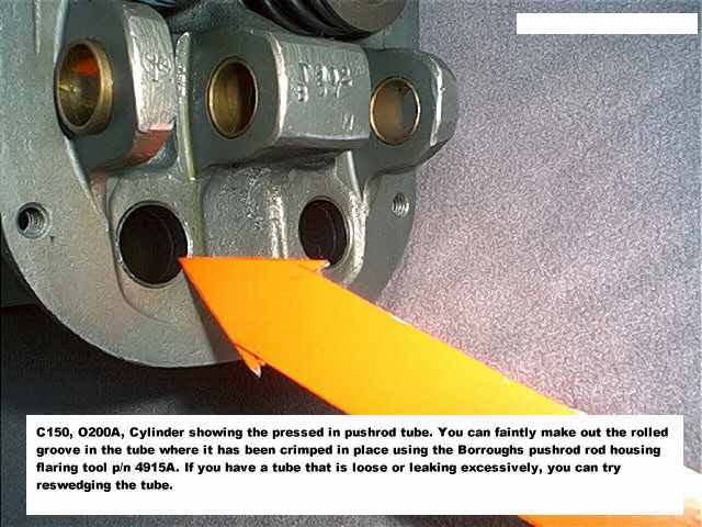
There is a tool which can be used to re-roll the pushrod tubes into the cylinder head with the cylinder installed. It is manufactured by Borroughs Tool & Equipment Corp. If your leak is in this area you may be able to stop it or slow it down by doing this.
Rocker box (valve cover) wear from the
rocker shaft
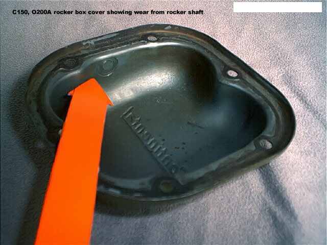
Continental designed the
rocker arm shaft so that it was retained in place by the stamped steel
cover. But the shaft tends to turn and usually ends up bearing hard on
one side or the other of the rocker box cover. Eventually it just eats
it way thru the cover. There is no fix for this, other than to be aware
of it and to possibly swap covers around when they are removed so that
the wear does not continue in the same spot for a prolonged period of time.
Continental did fix the problem when they introduced the new p/n 653816A3
cylinder assembly. The fix was the installation of a set screw in the boss
between the rockers which locks the shaft in place.
Cylinders
Over the years most operators
of 150's have found that 500 hours was about all one could expect from
the cylinders. The most common problem was a loss of compression which
is caused by excessive wear of the cylinder bore at the combustion chamber
end (open choke) caused by the rings reversing direction with the piston
as it reaches TDC. The bore eventually becomes so worn that the rings expand
out of their grooves until they jam and break, causing a loss of compression.
This is much more prevalent on this engine than other models of Continental
or Lycoming engines. As the total time on the cylinders accumulates, cracking
and head separation became more of a problem. It is quite common to find
the cylinder head cracked from valve to valve, valve to spark plug, or
plug to plug. In the past it was common to have the cylinder welded up
and reconditioned and reinstalled. There are so many problems with these
cylinders; valve seats coming loose in the head, valve guides coming loose
in the head, the cracking in the combustion chamber, valve and plug areas,
and the rocker shaft bosses being cracked, plus the excessive bore wear,
that it is best to install brand new cylinders.
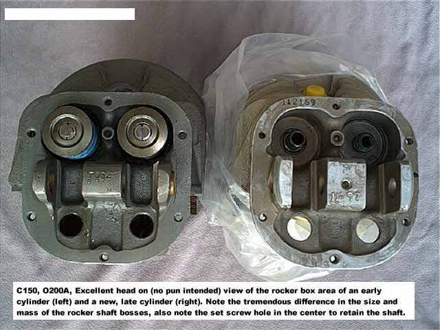
Note: The new cylinder on the right has the valves removed to comply with TCM CSB 98-1B, where Continental, during a period of time in 1997 and 1998 received some improperly hardened valves. I removed them and sent them to Continental, and they are sending me new, inspected valves to replace them. But YES, the cylinders do come complete from Continental with the valves, springs, etc. installed.
The new Continental p/n 653816A3 cylinder kit has a cylinder assembly with a heavier head casting, has the rocker shaft retaining set screw, and has the new removeable pushrod tubes. The assembly comes complete with a piston and pin, rings, rocker shaft, pushrod tube kit, and gaskets. All you reuse is the rocker arms, the rocker box cover and pushrods, and for not much more than overhauling your old cylinders would cost.
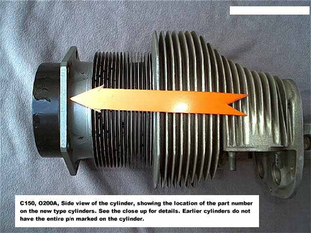
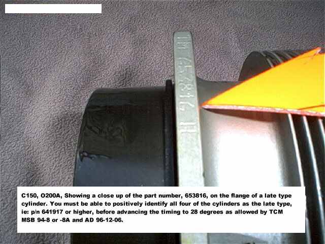
The best part of this is the relief you get from AD 96-12-06. This AD supersedes a AD 77-13-03, both of which require the timing to be set to 24 degrees BTC. The engine was originally certified with the timing at 28 degrees BTC. If you install a set of four Continental cylinders of p/n 641917 or higher the timing may again be set to 28 degrees, giving a noticable increase in power. Look on the edge of the mounting flange of the cylinder for the p/n, if none is present refer to TCM MSB 94-8A (link below) for illustrations on how to identify the "improved" cylinders. Reference TCM Mandatory Service Bulletin 94-8A dated 10/9/96 or later for information on identifying the cylinders and p/n information.
Another means of legally turning your timing back to 28 degrees is to install a set of four Superior Millenium cylinders, or ECI's Classic Cast cylinders, as the AD only applies to certain cylinders manufactured by TCM Continental. The ones manufactured by the other companies are all FAA-PMA approved as equivalent to TCM p/n 641917 or higher and thus are not affected by the AD.
Carburetors
Loose two piece venturis,
real or imagined? Well they were real enough to prompt the FAA to issue
AD 93-18-03 which mandated the replacement of the two piece venturi used
in various Marvel Carburetors for decades, with a one piece design, which
also eliminated the three retaining clips. The intent of the AD was good,
but few mechanics were finding loose venturis when they disassembled the
carbs to replace the venturis, which had to be done within four years.
After lots of screaming and yelling, the FAA relented and said that anyone
who still had the two piece style could continue to operate it indefinately
providing they preformed and annual inspection of the carb to insure the
venturi was not becoming loose. Of course, by this point most operators
had already replaced the venturi.
For those of us who did install the one piece venturi in the MA3 used on the O-200A, most experienced excessive richness and its associated high fuel consumption, roughness in flight, and a host of other disturbing quirks. This was apparently caused by poor quality of the venturis, many were rough, and some were unevenly cast and porous. To answer this problem, the manufacturer of the carbs designed and released a new fuel atomizer nozzle, know as a "pepperbox" design. This was provided as a kit, p/n 666-942, and was given free to those who complained.
***to be continued***
Modifications (or..let
the fun...and the expense begin)
Oil filters
There are a variety of different
oil filter kits on the market.
Cessna has an adapter which can be installed in the place of the screen in the back of the engine, onto which you install a spin on full flow oil filter. Cessna markets this as an Accessory Kit (AK), however, this adapter will not fit all model 150's as the filter will not clear the engine mount tubes on the older models with the engine mount with five mounting points on the firewall. The other problem with this adapter is that AD 96-12-22 applies to this adapter, even new out of the box, and requires the adapter to be properly torqued (with a special $50 crowfoot and torque wrench) and saftied, and inspection or torque putty be applied on all joints and safety wire. Each time the filter is changed and at intervals not to exceed 100hours the putty must be inspected for cracks. If you find the putty cracked you must check the torque on the adapter and if less than limits, remove the adapter to inspect it, plus you have to make log entries specific to this AD every time you change the oil.. WHAT A HASSLE. Oh by the way, if you buy the kit, it cost about $300 more than buying the adapter and the jamnut and o-ring as seperate parts. Pretty expensive box!
There is an easier way to filter your oil, and it fits on all model 150's. El Reno Aviation, P.O. Box 760 El Reno, OK 73036-0760, 1800-521-0333 markets an adapter that bolts directly to the case of the engine and takes a spin on CH48108 oil filter. This adapter is made by F&M Company and is also marketed by several other companies, including Wag Aero. It doesn't get any easier. Its the model TAF and is approved under STC SE7559SW. Continental designed the O-200 for an oil cooler to be directly mounted to the engine behind the back left (no. 2) cylinder. If you look behind the baffle just behind no. 2 cylinder, you will find a bulged cover held on by three nuts on studs. If you remove the cover you find two holes (oil passages) beneath it. The lower hole goes directly to the oil screen housing, it is oil coming from the pump then the screen and on its way to the engine. It passes out the lower hole, runs around under the cover and re-enters the engine thru the upper hole and goes to the left and right oil galleries, which supplies the lifters, camshaft and crankshaft with oil. The catch is, the only oil coolers that were ever installed on the O-200 were on 150 float planes, and most of them have been converted to 150 horse Lycomings. The rest of the engines have this "runaround" and that is where the El Reno's full flow filter adapter installs in the place of the cover. Its easy, simple and reasonably priced, and it works. Best of all you have the option of de-soldering the screen from the brass cap and installing the brass cap forever! I highly recommend this kit. Be sure and get the correct kit as they market a shorter adapter for C75/85/90 engines used in Ercoupes, Luscombes, etc. but it won't clear the 150 engine mount. You must get the O-200 kit. This kit is also marketed by Wag-Aero, and sells for around $200.
There are other kits which mount the oil filter on the firewall and connect it to the engine with flex hoses, but why bother? You have hoses to get loose and leak or fail, and the additional stress on the firewall, especially when loosening and tightening the filter will eventually crack the firewall and it creates more clutter in the engine compartment. If this is what you want, go seek it out, Air Wolf and others do market kits. The Airwolf kit is also STC'ed for the O-200 and sells for nearly $500, depending on who you buy it from.
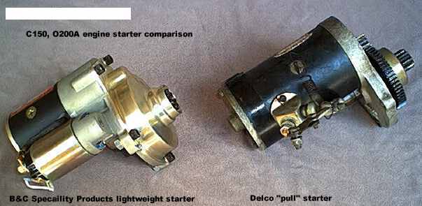
Starters
You keep seeing the ads
for those lightweight starters for Lycomings and wished you could do something
to lighten up the 150 a few pounds? Well, B&C Specialty Products, Inc.,
123 E. 4th, Newton, KS 67114 316-283-8000 markets a lightweight starter
for the O-200. The older 150's were equipped with the Delco "pull" starter,
which is a tractor starter adapted to an airplane engine. Its Heavy. You
can remove about 5 lbs. by installing the B&C starter. There is a catch
though. You must saw off the starter drive guide shaft that is installed
in the engine for the Delco starter, and this requires removing the oil
tank, magnetos, generator and starter and the accessory housing plus masking
off the entire back of the engine to keep metal chips out of it. A friend
of mine recently did this to a local flying club airplane. I told him I
wanted to see how well it cranked the engine and his reply was something
to the effect that you no longer needed any gas, just a strong battery,
it turned so fast it could fly on the starter alone!!!
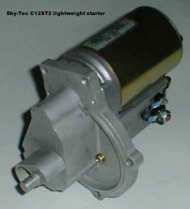
Eventually I'll revise this entirely, but for now I'm just going to add to this starter discussion. Sky-Tec, a manufacturer of "super fly-weight starters for GA aircraft" has recently introduced a new starter for the Continental O-200 engine ("The starter is PMA approved for C85-12, C90, C145, O200, and O300 A, B, & C that have been "converted to key start". What that means is up to your IA." to quote Les Staples at Sky-Tec). The starter is a direct replacement for the Prestolite unit used on the O-200 in Cessna 150's and installs without removing the bearing in the case (it has an aluminum "plug" on the snout of it that fits into the bearing, The purpose of the "plug" is to prevent an excess flow of oil from the bearing, causing a lowering of oil pressure, especially in engines with marginal oil pump flow and pressure). The Sky-Tec unit, p/n C12ST2, weighs 9.5 lbs and is FAA-PMA approved as a direct replacement for the Prestolite "key start" unit. Les tells me that the Feds say that this means that it can be installed with only a logbook entry and does not need an STC or completion of a Form 337.
This Starter can also be used to replace the Delco "pull starter". Sky-Tec has the STC application pending approval for the replacement of the Delco starter and should be approved in August or September of 2002. Sky-Tec has developed and installation kit which includes a push button and wiring and instructions. It does not need an external relay as used on the original Prestolite installation, and one is not included.
Visit Sky-Tec at www.skytecair.com
One last note, the Sky-Tec starter is used by Continental on the IO-240 engine.
Air Filters
This is really an airframe
item but most people regard it as engine so I have included it here.
Walk down the flight line at the local airport and look at the Cessna and Bonanzas and other aircraft that have exposed air filters. How many foam element filters do you find? A whole bunch. There's a reason for this. The paper filters used in the 150 are a rather poor excuse for an airfilter and are rather pricey ($50+). In fact the filters were (and still are) so overpriced that many owners tend to ignore them, or ocassionally remove them and blow them out. It became such a problem that the FAA got into the act and ANY paper induction air filter on any aircraft is subject to AD 84-26-02, which establishes a life limit of 500 hours for paper filters. For less money (about $35) you can purchase a Brackett Air Filter kit, which is an aluminum frame that mounts to the airbox with screws and self-locking nuts. You then install an oil soaked foam filter element and attach the front retaining grille. After that you need only buy replacement filter elements for about $6 to $8. You are doing your engine a favor by giving it well filtered air, and yourself a favor in the money department. The Brackett kit p/n is BA-4106 for 150's and 152's, and the replacement element is p/n BA-4108. If you have or have obtained an older Brackett filter kit, you should check if for compliance with AD's as there are several affecting the Brackett filters.
There are a couple of things you should know about the Brackett filters. First, when you first install the kit your mechanic must do a log entry, and complete a FAA Form 337 and have an IA sign it. In addition to that, the filter is subject to the maintenance requirements specified by the STC (and spelled out on a label on the filter housing) that you MUST replace the filter element every 100 hours or 12 months, or the filter becomes UN-airworthy. You may NOT clean and reuse the element. The only legal way to "prove" the filter is airworthy is to have a log entry showing that a new filter element was installed within the past 100hr/12mo, and your mechanic will need to do this, as FAR part 43's list of pilot preformed preventative maintenance items includes fuel and oil filters but not air filters, duh.
You also should be aware that early manufacture Brackett filter kits are subject to a couple of different AD's themselves.
Crankcase breather improvement
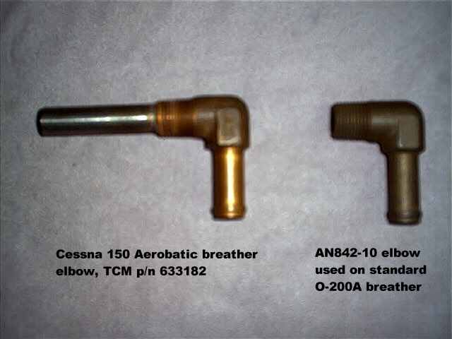
For those of you tired of oil on the belly and don't want to go to the hassle and expense of installing an oil/air separator (such as the M20 unit), you could install an aerobatic breather elbow that was used in Cessna 150 Aerobats. Its is a standard brass elbow milled out to accept a steel tube which is then silver soldered into the elbow. The Continental part number for the aerobatic elbow is 633182 and the part number for the standard elbow is AN842-10 which is a standard part.
Beware that several years ago someone manufactured a number of bogus aerobatic elbows and you should obtain a known legal part, either removed from an aerobat engine or new from a Continental parts distributor.
Below are three pics, the first is a comparison of the two elbows.
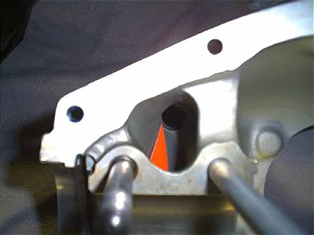
The next pic is of the inside of the Right Hand side of the O-200 engine case showing the opening where the elbow is screwed in from outside. This is a well shielded area that only gets oil spray coming off the front of the main bearing below it. (note the channel just above the LH stud in the photo, where oil coming from the front of the front main bearing is thrown by the oil slinger on the crankshaft out thru this channel and one like it below the bearing).
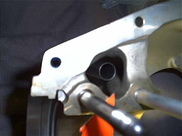
This pic shows the same view with the aerobatic elbow installed. It would be much more difficult for oil to find its way into the end of this tube suspended in mid-space than the standard elbow, where all the oil has to do is run down the top of the case till it reaches the hole and is drawn out by airflow.
Here is a testimonial of sorts about the aerobat crankcase breather fitting. In the early summer of 2001 several folks got together and ordered the aerobat crankcase breather fittings from Continental. They were able to get a slight discount by ordering in quantity and what follows is a posting from the 150-152 club discussion group on Yahoo about one person's initial experience with the new breather fitting. It is from Sam Rosenfeld. (July 15, 2001, post #7943)
"Installed the Aerobat breather about 2 weeks ago. Some results (not at all scientific): 1. Drip test - upon shutdown - I swear I now get only about half as many drops of oil than before. 2. Belly test - not sure but it seems that I get much less blowing out the breather and onto the belly than before. The real test I guess will be how much oil I'm adding over time - can't tell after just 6 or 7 hours . . . So far though - it seems to be quite an improvement!! Sam 150K - 6001G"
Another testimonial of the aerobat crankcase breather fitting, this one from Mike Bratton, about his 1965 150E, from the Cessna 150-152 Club Discussion Group on Yahoo, (April 3, 2002, post #18198)
"Installation of the aerobat breather tube resulted in going from a
average oil consumption of 3 hours per quart to 7 hours per quart of oil. This
plane also has the wet vacuum pump which accounts for some oil blown overboard
also.... All in all very happy with both changes I made last year. Of course your mileage
and results may differ.... Mike Bratton N3577J C150E"