Email me at hannacm@charter.net
Visit Charles' and Dusty's homepage
Return to the Early Cessna 150 Inspection Homepage
150 home / Charles's Home / Misc Items / MLG Insp / Firewall / Rudder & Vertical / Tailcone / O-200 / O-200 Oil Flow / Props / Jacking / Shoulder Harness / Links / Owner Mfg Parts / Owner Maintenance / IO-240 Dream Engine
Firewall Inspection
Legal stuff: The material presented below is for educational/entertainment/reference use only and should not be used as documentation in the inspection and repair of any aircraft. You should always consult the Manufacturers FAA/CAA approved documentation such as Maintenance Manuals, Service Letters and Bulletins, Kit instructions, STC's, etc. for inspection and repair information and procedures. I make no claim or warranty as to the accuracy or completeness of the material presented, and accept no responsibility for its use or misuse. Also, this web page or any other of mine, is not connected with, or approved or sanctioned by Cessna Aircraft Corp. or any other entity named herein. Charles M. Hanna
The pics on this page are "thumbnails" to make the page load faster, I thought I would try this as an experiment with one page. Let me know if you think it is a good idea or not.
The firewall is easy to inspect for problems as everything you need to see is on the engine side. Yes you should look at the structure on the back side but it does not have any unusual problems.
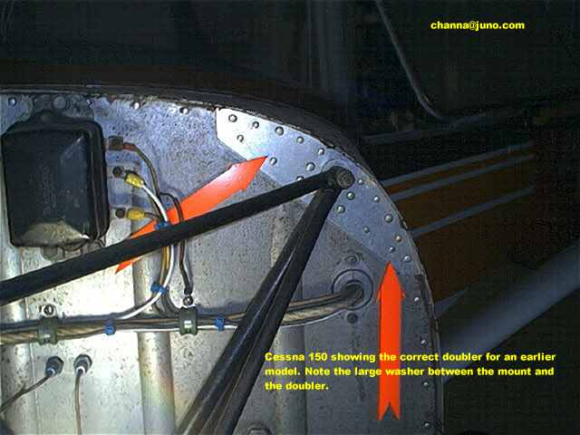
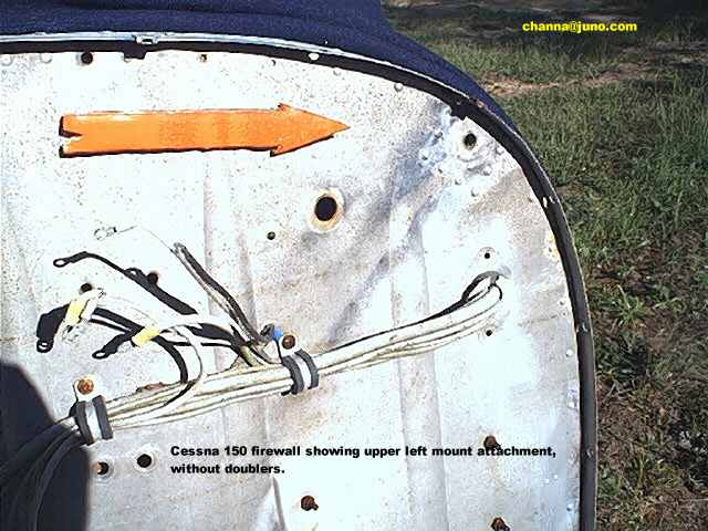
The Cessna 150's thru the end of the 1966 models (150F) have five engine mount/nosegear mounting points on the firewall. The four in each "corner" and one in the top center. Later aircraft have only the four "corner" attachments. The mount for all aircraft using the the five point attachment are interchangeable except the mounts used on s/n 59216 and later (a midyear 1961 150A) require a washer between the mount and the firewall as the mount was made shorter by the thickness of the washer. It is a good idea on earlier models to install the washers anyhow as it provides a more solid place for the mount to be tightened up againist and the thickness of a washer is not enough to cause any problems.
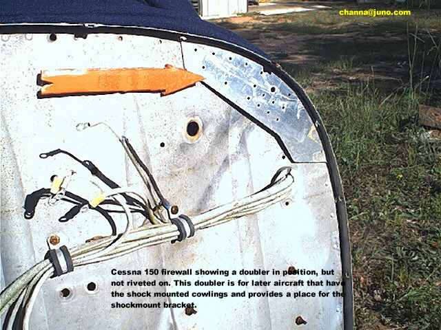
Beginning with s/n 61640 (a midyear 1966 150F) doublers were installed as standard equipment on the firewall at the engine mount attachment points. these were made of about .125 thick aluminum and added several rivets and provided a substantial improvement in strength. These doublers first appeared in mid 1964 (150D) on aircraft equipped with the heavy duty nose gear, which is nothing more than a Cessna 206 piston and fork assembly installed in a standard 150 strut cylinder. The fork uses a 6.00x6 wheel and tire and the fork, strut cylinder and steering collar are installed with the torque links facing forward.
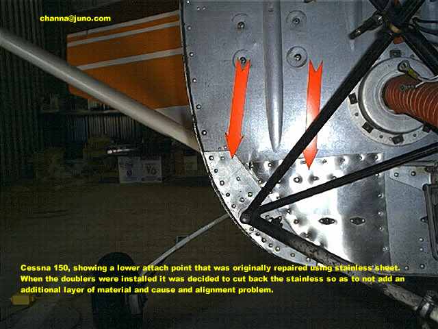
As to inspecting the firewall, examine it closely for cracks or wrinkles, expecially in the area of the lower engine mount to firewall attachment. If only small cracks are found, and there are no doublers installed, I would suggest stop drilling the cracks and installing the doublers. Cessna Service Letter 65-94 approves the installation of these doublers as a set on aircraft not already equipped. The p/n's are 0453116-1 and -2 and -3 and -4. New mount bolts and p/n S1450-5-18-063 washers should also be installed. Something not addressed by the SL is the fact that the top center attachment will need a spacer of the same thinckness as the doublers and washers combined, and a longer bolt will be needed. At least one of these doublers was no longer in stock at Cessna about 20 years ago, and I would be suprised if any of them were now. They could be easily fabricated using another aircraft for patterns, but it would be necessary to contact Cessna to find out what material to use.
Anyhow, here are several shots of firewalls with and without doublers.
Click on the fingernail pics for the full size image.
Use the BACK button on your browser to return to this page.