Page last revised 12/25/02
Oil Flow 101 for Cessna 150 and O-200A
Owners
Email me at hannacm@charter.net
Visit Charles' and Dusty's homepage
Return to the Early Cessna 150 Inspection Homepage
150 home / Charles's Home / Misc Items / MLG Insp / Firewall / Rudder & Vertical / Tailcone / O-200 / O-200 Oil Flow / Props / Jacking / Shoulder Harness / Links / Owner Mfg Parts / Owner Maintenance / IO-240 Dream Engine
Legal stuff: The material presented below is for educational/entertainment/reference use only and should not be used as documentation in the inspection and repair of any aircraft. You should always consult the Manufacturers FAA/CAA approved documentation such as Maintenance Manuals, Service Letters and Bulletins, Kit instructions, STC's, etc. for inspection and repair information and procedures. I make no claim or warranty as to the accuracy or completeness of the material presented, and accept no responsibility for its use or misuse. Also, this web page or any other of mine, is not connected with, or approved or sanctioned by Cessna Aircraft Corp., Teledyne Continental Motors (TCM), or any other entity named herein. Charles M. Hanna
This page is layed out from the beginning with the oil entering the suction tube in the tank and traveling thru the entire oil system, in the correct sequence. At the end is several pics showing the vacuum pump drive lubrication, the Prestolite starter drive lubrication, the mechanical oil temp bulb as it installs in the oil screen and the problem with the thin, easily damaged (and irreplaceable) nut that must be removed each time the oil screen is removed,
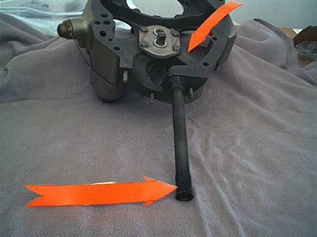
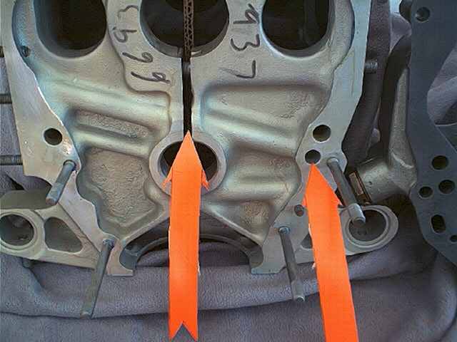
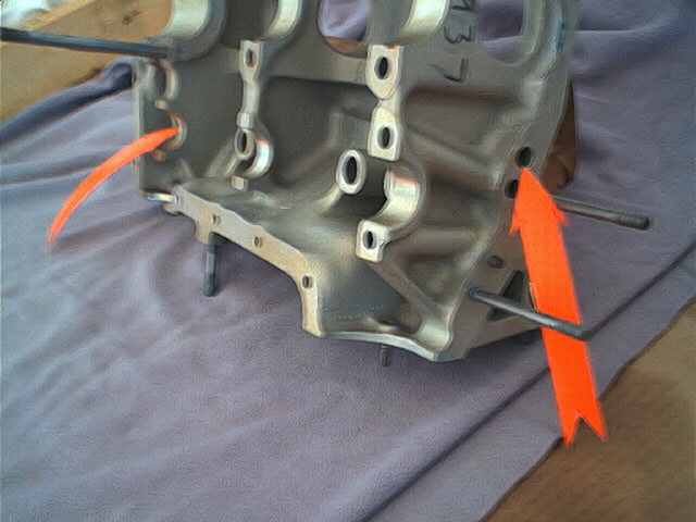
BELOW The oil is sucked up from the oil tank thru a pickup tube (bottom arrow) and enters the bottom of the accessory housing, flowing thru a cast passageway in the Left hand side of the housing (your right as viewed here, top arrow) and enters the pump (already assembled here with gears and cover plate).
BELOW The oil exits the pump into the housing for the oil screen (not visible on the back of the cover) via another cast in passage way (left arrow)
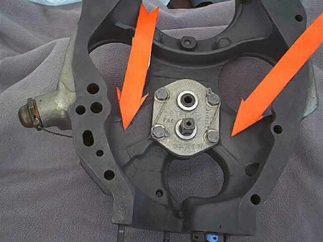
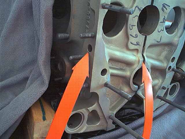
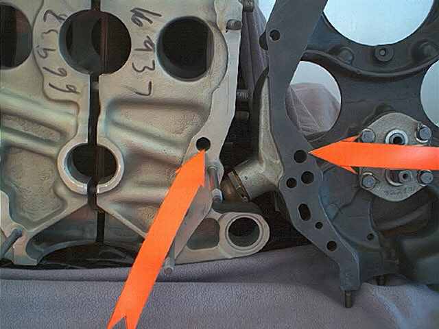
BELOW After passing thru the screen (if installed) it exits the center of the screen and travels thru another cast passage and exits the accessory housing at the hole indicated by the arrow (on the right) and enters the right side of the rear of the case at the arrow (on the left). The oval hole in the accessory housing below the one with the arrow is also oil from the screen housing, but is blanked off by the gasket and case and serves no purpose.
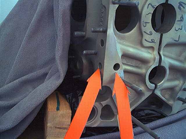
BELOW The oil enters the case at the arrow (on the right) and makes an immediate left turn and travels across the case to the left side of the case at the pad where either a "runaround" cover is installed or the "ElReno" oil filter adapter is installed. The arrow (on the left) indicates the bulge in the casting where the passage is drilled and also the place where the two halves of the case meet and the passage joins. This is a potential oil leak area as there are no gaskets, o-rings or anything other than some sealant smeared on the mating surfaces at assembly to seal this joint. If it does leak you will never know as it is internal, but will cause a loss of oil pressure.
Where the oil enters the case at the right arrow, it meets the cross drilled passage and there is no connection between this passage and the oil gallery located just above it in the right half of the case.
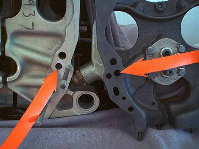
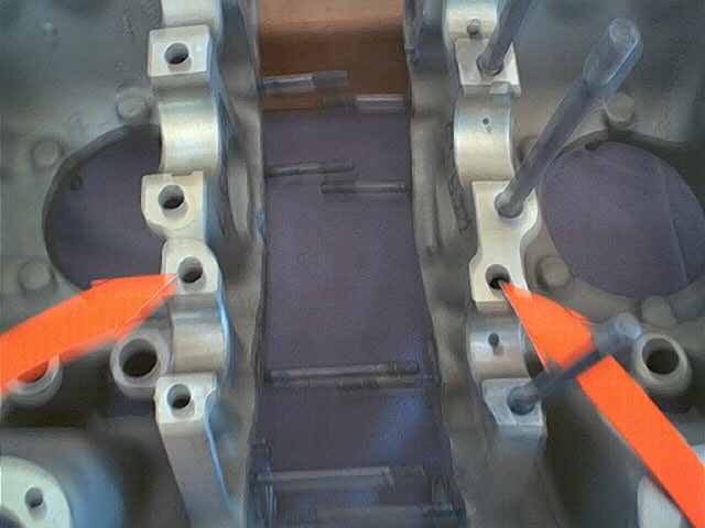
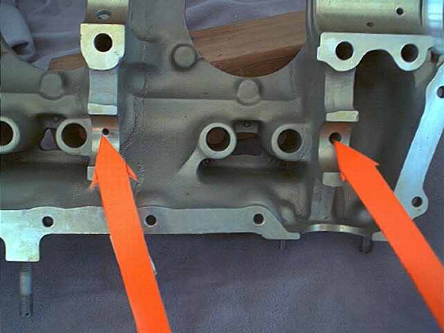
BELOW This shot shows both halves of the case showing where the crossover passage holes are located just above the camshaft rear bearing.
BELOW This shot shows the crossover oil passage from the center of the case to the hole where it exits (top arrow).
You might wonder why Continental went to so much trouble to bring the oil in the right side of the case and then cross it over to the left side? Well if you look at the oil flow in a C75 or C85 -8 model engine, which is not equipped for a starter or generator, the oil pump turns opposite the pump on -12, -16 and O-200 engines, as the pump was positioned in the accessory housing differently and on the -8 models the top gear in the oil pump is the driven gear and in the -12,-16, and O-200 models the lower gear of the pump is the driven gear (the pump was moved up to make room for the generator) In any case this reversed the flow of oil thru the pump. Nowadays we would just manufacture the case differently, but in the 1940' and '50, making new tooling to drill all the oil passages in the case for the camshaft and crankshaft in the right side rather than the left side would have been difficult and expensive. Besides tooling already existed to drill up the left side of the case correctly, so the fix was to have the oil transverse the case to get back to where they needed it to enter the oil gallerys at. Thus the crossover passage shown here.
BELOW This shot shows where the oil reenters the case (left arrow) after passing thru the runaround cover or the "ElReno" oil filter. it intersects with the oil gallery running the length of the left side of the case (right arrow).
BELOW I thought this would be a good place to show what the "ElReno" oil filter adapter looks like. This adapter is actually made by the F&M Company of Borger, Texas, and is marketed by several different parts vendors. El Reno offers Cessna 150-152 club members a 10% discount on it. It attaches over the two holes above the left arrow in the shot above and attaches with the three studs (one is hidden by the left arrow above). When it is installed, oil exits the top hole on the left side of the case and passes thru the oil filter, exiting the filter from the center, and reenters the engine via the lower hole, left arrow above. This adapter uses a CH48108 filter (Champion) or ES48108 (Electrosystems) which has an internal bypass feature. Do not use other number filters, even if they screw on and fit properly, as they do not have the internal bypass.
BELOW This shot shows the oil passage where the center camshaft bearing is lubricated with a oil passage (left arrow) drilled to intersect the left main oil gallery. The aft camshaft bearing and all three crankshaft main bearings all have similar drilled passages intersecting the left main oil gallery. The (right arrow) shows the much larger passage which lubricates the front camshaft bearing and allows the oil to crossover to the right side of the case. The camshaft itself at the front bearing journal is grooved all the way around to allow the oil to pass around it enroute to the right side.
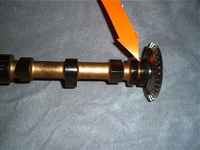
BELOW This shows the front bearing journal on the camshaft, which is grooved to allow a large quantity of oil to flow around the camshaft unrestricted, to the other side of the case.
BELOW This shot shows where the oil enters the right side of the case at the front camshaft bearing and then passes thru to the right main oil gallery.
BELOW This shot shows where the oil enters the right side of the case (left arrow) at the camshaft front bearing and passes into the right main oil gallery which feeds the lifters and nothing else in this side. The (right arrow) aft end of the oil gallery exits the case just above where the oil entered earlier (but these two passages are not connected here or in the accessory housing) and passes into the accessory housing and stops at the relief valve/pressure regulator, which if needed "blows off" excess pressure into the accessory housing just under the right magneto and aids in lubrication of the drive gears.
BELOW This shot shows where the oil exits the rear of the right main oil gallery (left arrow) and enters the accessory housing (right arrow). The oil does not go anywhere other than the relief valve in the accessory housing and this passage is not connected to the one below it.
The oil pressure port for the gauge connection is located in the outside of the case just forward of the left hand arrow. Thus the oil pressure you see on the gauge in the cockpit is the LOWEST pressure in the engine, at the very end of the oil passages. And this is why it takes so long for pressure to build up after starting. If you were to tap a pressure gauge in at the oil temp bulb/oil screen, just downstream from the pump, you would probably find substantially higher oil pressure readings.
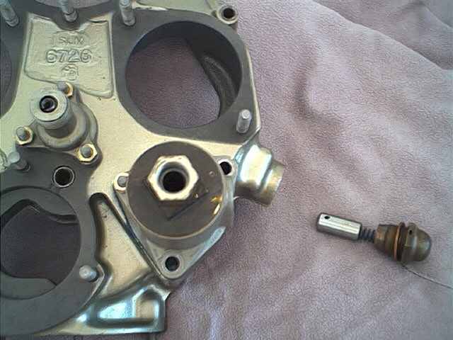
BELOW This shows the oil pressure relief valve/regulator valve removed from the accessory housing, showing the plunger, spring and cap, which is the spring and plunger guide. Also note the oil screen and oil temp bulb adapter installed in the screen housing in the accessory housing. If a Cessna oil filter adapter is installed, it takes the place of the oil screen entirely, screwing into the screen housing. The Cessna oil filter adapter is the subject of an AD (even new out of the box) and requires that each time you change the filter, you check the adapter housing for looseness and look for broken inspection putty/torque seal ("bird poop" to us mechanics) and if the putty/seal is broken, the adapter must be inspected for cracks and re-torqued in place. After each filter change a log entry specific to the AD must be made, showing compliance with the appropriate paragraphs of the AD. (Sorry, I cannot scare up a Cessna adapter to show you) Other full flow filter systems, such as the AirWolf consist of an adapter which installs in the place of the screen and a filter mounting adapter which installs on a firewall mounted bracket with hoses connecting it to the engine adapter.
Also, the Cessna oil filter adapter cannot be used on early 150's which have the five point engine mount (to firewall) as the tubes of the mount are positioned differently (than later four point mount to firewall installations) and the filter adapter cannot be rotated to where the filter will clear the engine mount tubes of the older mount.
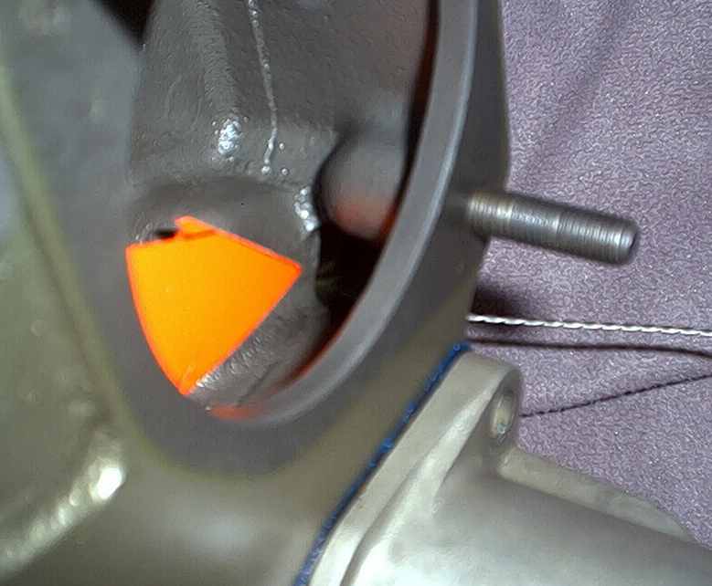
BELOW Looking thru the right magneto mounting hole, at the tip of the arrow, is the opening where excess oil pressure from the relief valve is returned to the gearcase and thus the oil tank, aiding in the splash lubrication of the gears in the process.
BELOW This shot shows two holes at the tip of the arrows where oil enters the lower hole (lower arrow) from the rear main bearing and passes thru to an intersecting oil passage which exits at the top hole (top arrow) to supply oil to the Prestolite key starter drive gear. The Delco and B&C starters do not need this passage and you must reinstall the cut off portion of the Delco drive gear support with sealant to blank off the top hole when installing a B&C starter, or in some way blank the hole if you removed a Prestolite starter, so you don't have a continuous internal oil leak. This was done as a service bulletin modification and later at the factory during production, so all cases may not have this passage.
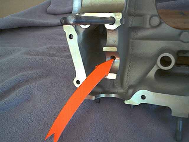
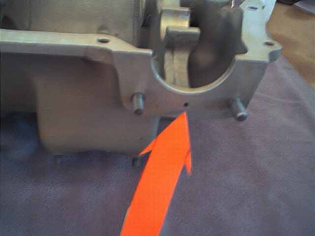
BELOW This shot shows the oil passage from the left crossover passage near the front camshaft bearing to the vacuum pump drive adapter pad, to supply oil to the vacuum pump driven gear and bushing and if you have a wet pump, to the pump itself.
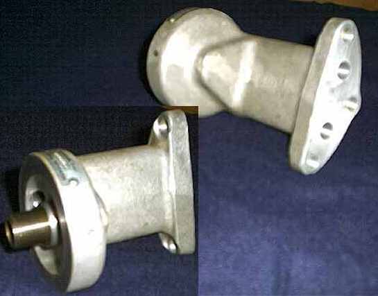
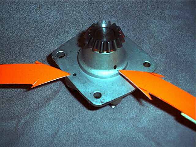
Below This shows the vacuum pump drive adapter (engine internal side) that bolts to the bottom of the case (see above pic) the (left arrow) hole on the left is where oil under pressure enters the adapter from the hole shown in the above pic. The (right arrow) hole on the right shows the hole where oil exiting the driven gear bushing returns to the bottom of the case. This is a low spot in the case, and oil will always stand on top of this adapter and cannot be drained out, so should you ever have to remove it, be prepared.
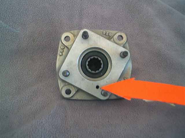
BELOW This shows the hole on the vacuum pump drive pad (engine external side) where some of the oil under pressure exits to the vacuum pump itself (if you have a wet pump). If you have a dry air pump or none at all, you must install the dry pump or blanking plate using a gasket so as to seal off this oil hole, or you will have a tremendous oil leak. NEVER run an engine with the vacuum pump removed, unless the mounting pad has been properly blanked off with a gasket and cover plate.
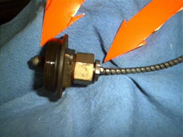
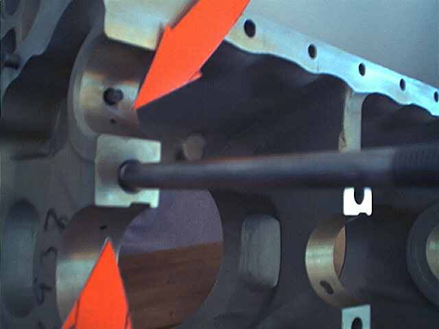
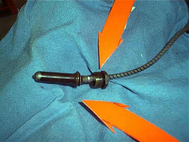
BELOW The oil temp bulb/gauge system on older 150's is mechanical and the temp bulb, tube and gauge is one inseperable part. Loose on the tube above the bulb (lower arrow) is a hollow "nut" (upper arrow) which retains the bulb in the adapter on the rear of the oil screen. This nut is very thin, the hex is only about 1/8 inch wide, and fragile, as it is of course, hollow and easily collapsed. If damaged the entire gauge and tube/bulb must be changed as a unit and this assembly is irreplaceable as none can be purchased new. The John Wolfe Company is in the business of repairing old instruments such as this and I have been told of a couple of first hand accounts of Cessna owners having their instruments successfully repaired by them.
BELOW This shows the temp bulb screwed into the adapter on the back of the brass screen "nut" (the screen has been desoldered, or removed, following an oil filter installation).