Email me at hannacm@charter.net
Visit Charles' and Dusty's Homepage
Return to the Early Cessna 150 Inspection Homepage
150 home / Charles's Home / Misc Items / MLG Insp / Firewall / Rudder & Vertical / Tailcone / O-200 / O-200 Oil Flow / Props / Jacking / Shoulder Harness / Links / Owner Mfg Parts / Owner Maintenance / IO-240 Dream Engine
Jacking a Cessna 150
Legal stuff: The material presented below is for educational/entertainment/reference use only and should not be used as documentation in the inspection and repair of any aircraft. You should always consult the Manufacturers FAA/CAA approved documentation such as Maintenance Manuals, Service Letters and Bulletins, Kit instructions, STC's, etc. for inspection and repair information and procedures. I make no claim or warranty as to the accuracy or completeness of the material presented, and accept no responsibility for its use or misuse. Also, this web page or any other of mine, is not connected with, or approved or sanctioned by Cessna Aircraft Corp. or any other entity named herein. Charles M. Hanna
This is a prototype page that is not by any means complete (I never seem to finish anything). I have thrown this together in a hurry to get some pics where they can be seen, and will make more pics and add to the pics and text of this page in the future.
Later aircraft have the tubular landing gear and while this site is oriented toward the "early" 150's, I will also add pics of the tubular gear jacking procedure when I find a couple to make photos with.
Normally you only need jack a Cessna 150 by the landing gear legs, for the purpose of changing a tire, cleaning and packing wheel bearings, or even re-shimming the axle for wheel alignment.
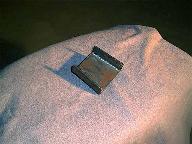
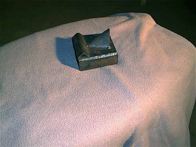
Here are a couple of shots of a landing gear flat leg adapter for the Cessna 150. This one is "homemade" but is an exact copy of a Cessna manufactured one, even down to having a p/n engraved in it!. It is TIG welded together and is a fine example of quality workmanship.
Sometimes even a lowly Cessna 150 needs to be jacked by the wings. This is actually something that should be done at every annual inspection, how else is the IA going to know if the gear is tight and secure? When the weight of the airplane is sitting on the gear, even a very loose gear seems tight.
Here are a couple of pics of a Cessna 172RG jackpad and the pad installed on a 150. The reason this works is that the 150 and 172's share many common wing demensions and rivet spacing is one of the commonalities of the two.
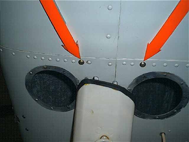
To install the 172RG jackpad, the third rivet forward and third rivet aft of the skin lap at the spar, at the rib just outboard of the wing strut need to be drilled out, and enlarged to 3/16 inch. For a real tight hole use a #12 drill instead. Enlarge it carefully so that the hole does not "walk" outboard, as it could become too close to the radius of the rib to use.
If the holes are well away from the radius of the rib inside the wing, you should only need to use thick aluminum washers (AN960PD3). Do NOT use regular 3/8" hex nuts such as AN365 nylon stop nuts, but instead use the little 1/4" hex "jet nuts" which will allow lots of room for a wrench. Check carefully with a mirror and bright light before tightening up the nuts, to insure the washers are not cutting into the radius of the rib inside the wing. If they are, you will need to take a small square of aluminum, about .190 to .250 thick, drill a 3/16" hole in it and radius the edge to fit the rib, thus fabricating a radius block. By all means, DO NOT DAMAGE THE RIB, EVEN SLIGHTLY. You should exercise extreme care in doing this.
The Screws used are AN525 "washer head" screws which are very low profile. On the ones I used to plug the holes when the jackpad is not installed, I used extremely thin AN960PD3L washers (the PD designates aluminum, the "L" designates thin, in this case it is 1/64 of an inch)
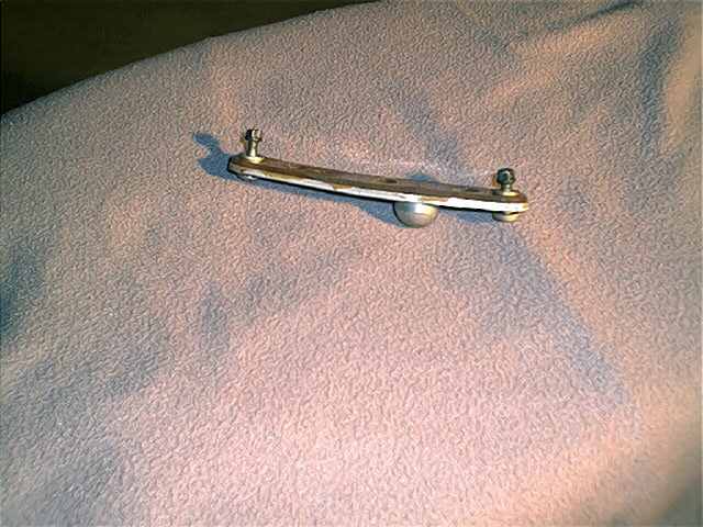
Here is the 172 RG jackpad, which has a thick, very stiff plastic backing. The raised jackpoint is welded to the flat portion of metal. The jackpad has a third screw hole, but it is not needed to securely mount the pad. My airplane sat on these for over a year while the gear was removed as I rebuilt the landing gear "box" structure.
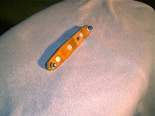
Here is a good view of the back side of the pad. The plastic is cut out to fit over rivet heads.
These are the "plug" screws installed in the holes where the jackpad attaches.
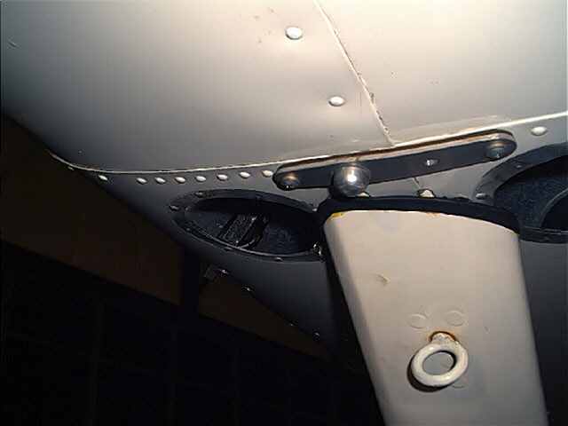
This is the installed jackpad.
In the future I will add photos of these jackpads in use, with lots of text on jacking a 150 by the wings.